
Last Updated: 7 May 2025
How To Wire a Peco SL-E399F Electrofrog Asymmetric 3 Way Turnout Crossing for DCC
Check out our downloads page for printable Peco Track Templates and drilling guides for baseboard wire routing.
Overview
This turnout allows you to go from one to three tracks in a small space. It comes with two bare metal 'tails' which provide power to the two frog 'zones' marked on the diagram in green and yellow. The dark spots on these areas show where the bridging wires are connected underneath. There are two moving switchblades, so you will require two MTB MP1 point motors.
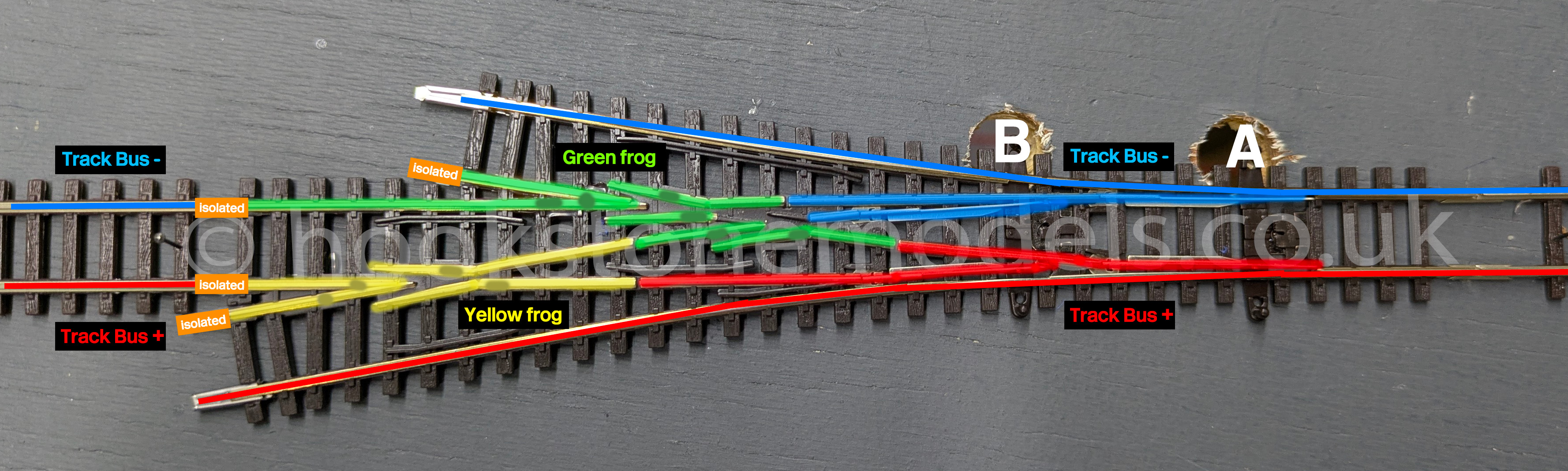
Step 1 - Connect Blue & Red to Track Bus
The blue and red zones are always the same polarity regardless of the route set, and match those of the very outer fixed rails. As such, these can be wired straight into your track bus. Note the use of insulated joiners on the left hand side, this is necessary and you will experience shorts if you use normal metal rail joiners there. On the diagram, the track bus connections are notionally labelled '+' and '-', because it's easy to understand.
Step 2 - Solder Wires to Green & Yellow Frog Tails
The green and yellow zones need to change polarity depending on which route is set. Cut the bare metal tails back and solder a wire onto each, applying a piece of heatshrink sleeving over the joint.
Step 3 - Fit Point Motors
Fit two point motors to your baseboards, and connect the COM, Poz1 and Poz2 terminals on each to your accessory decoder.
Connect the track bus power to the top two terminals on the MP1 motors, this should leave just the Aux1 terminal free, which is for the frog wires.
Step 4 - Connect Frog Power
Point Motor 'A' will control the polarity and power to the green zone, and Point Motor 'B' will control the yellow zone. Connect the Aux1 terminal of motor 'A' to the green frog tail. Connect the Aux1 terminal of motor 'B' to the yellow frog tail. Check everything is correct as per the table below with a multimeter. When A1 is set to diverge, the green frog should be connected to the red track bus. When B1 is set to diverge, the green frog should be connected to the blue track bus. It follows, then, that if A1 and B1 are both set to diverge, you will get a short.
| Point Motor | Route | Green Frog Connected To |
| A | Straight | Track Bus Blue |
| Diverging Right | Track Bus Red | |
| Point Motor | Route | Green Frog Connected To |
| B | Straight | Track Bus Red |
| Diverging Left | Track Bus Blue |
If your multimeter continuity does not confirm that you have everything connected as above, simply swap the track power wires going into the MTB MP1.